Introduction
In many electronic circuits, transistors are required to work together in pairs or groups, often performing the same function. For optimal performance, these transistors need to be as similar as possible in their electrical characteristics. This practice, known as transistor matching, is common in audio amplifiers, differential pairs, current mirrors, and bridge circuits. While integrated circuits (ICs) often include matched transistors fabricated on the same silicon die, discrete transistors from the same batch can still exhibit variations. Understanding how to match discrete transistors is crucial for hobbyists and professionals alike, as it directly impacts circuit efficiency and reliability.

Why Matching Transistors Matters
When multiple transistors share the workload in a circuit, mismatched parameters can lead to uneven current distribution. One transistor may end up carrying more load than its counterpart, causing inefficiency and potentially overheating the overworked device. The two primary parameters that require matching are current gain (hFE or β) and saturation characteristics (such as VCE(sat)). In differential amplifier stages, matched gain ensures that the output reflects the true difference of input signals without added distortion. Similarly, in current mirrors, matched transistors guarantee that the mirrored current accurately replicates the reference current.
Key Parameters for Matching
Current Gain (β)
Gain is the ratio of collector current to base current. Even transistors of the same part number can have gain values that vary by 20–50% across different units. For circuits that rely on precise current amplification—such as audio amplifier input stages—matching gain within 1–2% is often necessary.
Saturation Voltage (VCE(sat))
When a transistor is fully turned on (saturated), the voltage across its collector-emitter terminals should be low. Mismatched saturation voltages can cause one transistor to enter saturation earlier than another, leading to signal clipping or asymmetry in push-pull stages.
Base-Emitter Voltage (VBE)
For bipolar junction transistors (BJTs), the VBE at a given collector current is another matching criterion. In differential pairs, a mismatch of even a few millivolts can produce a significant input offset voltage.
How to Match Transistors
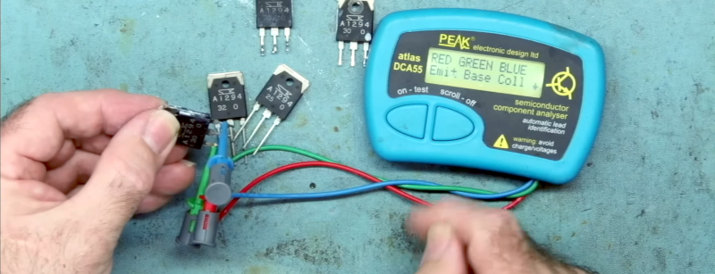
The process of matching discrete transistors typically involves measuring the target parameter (e.g., β) under controlled conditions and grouping devices with similar values. Basic setup includes a power supply, a multimeter, and a breadboard or transistor tester. For hobbyists, dedicated transistor matching jigs are available, but a simple circuit can be built to compare parameters.
Measuring Current Gain
To measure gain, you can use a circuit that forces a known base current (e.g., 10 μA) and measures the collector current. The transistor under test should be allowed to reach a stable temperature, as gain is temperature-dependent. Record the β value for each transistor and sort them into bins with a tolerance, say ±1%.
Testing Saturation Characteristics
For saturation matching, you can apply a fixed base current and measure VCE while the collector current is held constant. Again, group transistors with similar VCE(sat) values.
Using a Curve Tracer
More advanced methods involve a curve tracer, which displays the collector current vs. collector-emitter voltage family of curves for each transistor. Overlaying curves from different devices helps visually identify matches across multiple operating points.
Applications Beyond Transistors
Matching is not limited to transistors. In bridge circuits—such as Wheatstone bridges—resistors or capacitors often need to be matched to ensure accurate measurements. For example, two 10 kΩ resistors with a 10% tolerance could actually be 9 kΩ and 11 kΩ, causing bridge imbalance. By matching them to a close value (e.g., both 9.2 kΩ), the circuit's precision improves dramatically. This same principle applies to capacitor matching in integrators or filters, where time constants depend on component values.
Difference from Impedance Matching
It is important to note that transistor matching is distinct from impedance matching. In impedance matching, the goal is to maximize power transfer by making the load impedance equal to the source impedance (or its complex conjugate). Transistor matching, on the other hand, aims to equalize the behavior of two or more similar devices under the same conditions, regardless of the impedances involved.
Conclusion
Whether you are building a high-fidelity audio amplifier, a precision instrumentation circuit, or a simple current mirror, matching discrete transistors can significantly enhance performance and reliability. Although ICs often provide built-in matching, discrete designs require careful selection. By understanding the parameters that matter—gain, saturation voltage, and VBE—and employing straightforward measurement techniques, you can achieve consistent results. Remember that matching is a time investment that pays off in cleaner signals, lower distortion, and longer component life.